CAD Design of Metal Gear Shafts
We offer detailed CAD (Computer-Aided Design) diagrams of metal gear shafts as part of our comprehensive mechanical design and engineering services. These diagrams are essential tools for visualizing, fabricating, and assembling mechanical components with precision and clarity.
What We Provide:
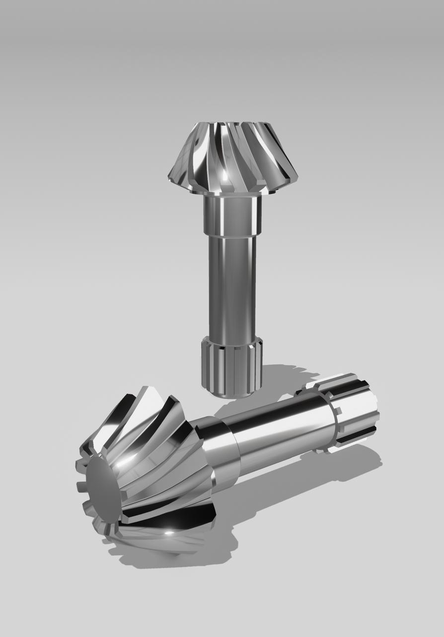
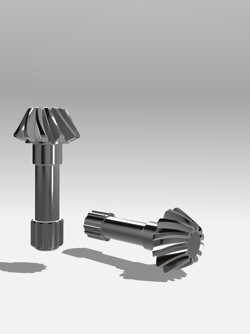
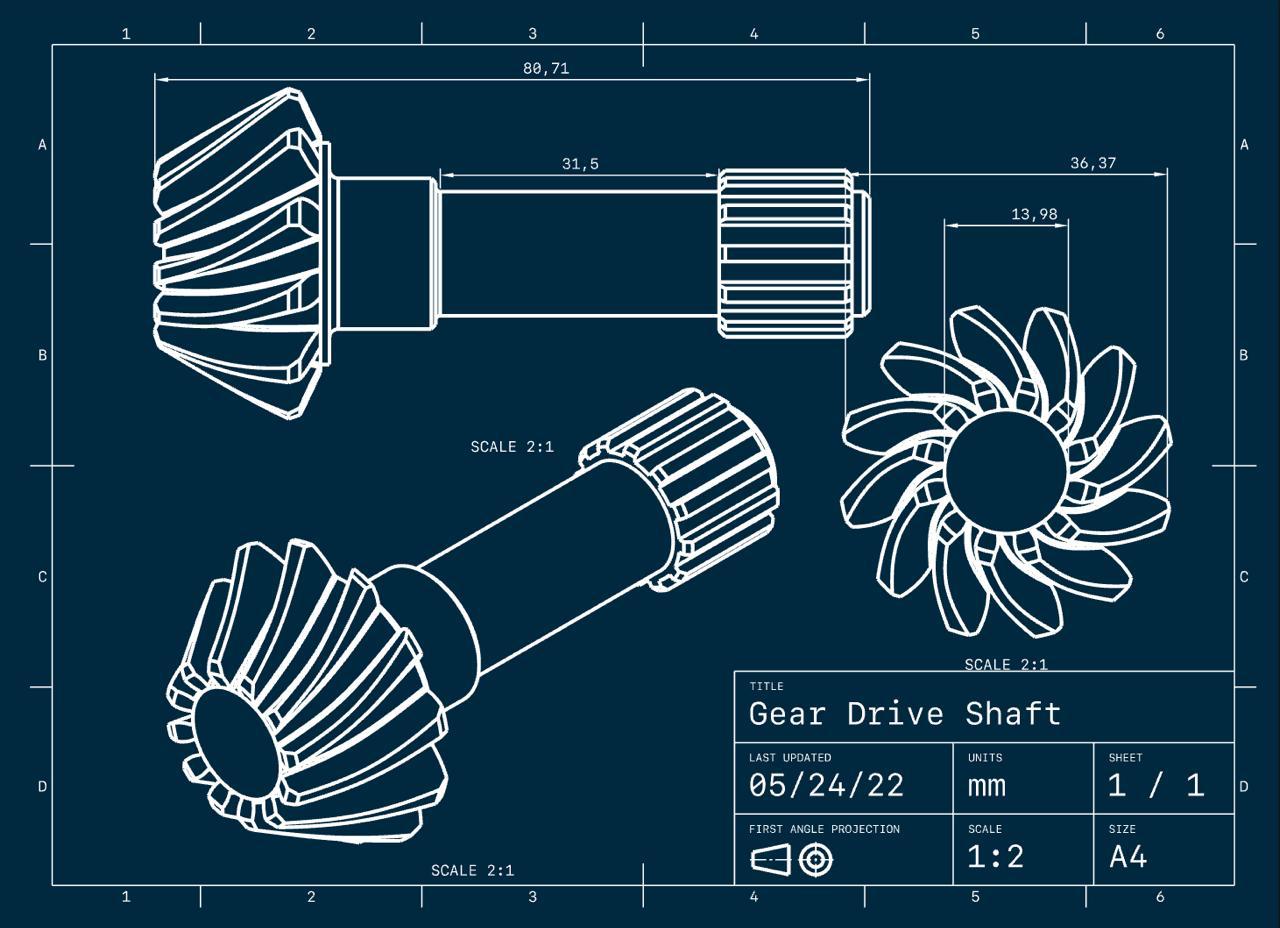
- High-Detail 2D & 3D CAD Models: Our experts create accurate and scaled representations of metal gear shafts, including all key features such as splines, keyways, gear teeth, shoulders, threads, and tolerances.
- Custom Specifications: Designs are tailored to client-specific requirements, including material type, gear ratio, torque rating, and shaft dimensions.
- Mechanical Simulations & Analysis: We can simulate load, stress, and rotation behavior using the CAD model to ensure optimal performance before actual production.
- File Compatibility: Models are delivered in standard CAD formats (such as STEP, IGES, DWG, or STL) for easy integration into client systems or machinery.
Why Choose Our CAD Gear Shaft Services?
- Improved Machine Design Understanding: Helps clients and operators visualize the part within an assembly and understand how it interacts with other components.
- Fabrication Ready: Our CAD drawings are production-ready, aiding in efficient CNC machining or manual fabrication with minimal revisions.
- Reduces Errors & Downtime: Precise modeling ensures better alignment, smoother operation, and reduced risk of mechanical failures.
Whether you’re designing a new machine or upgrading an existing one, our metal gear shaft CAD diagram services provide you with the technical clarity and engineering support needed for high-performance, reliable machinery.